
前回の「Vitis とは?」の記事で、Vitis の Tool について紹介しました。2回目となる今回は Vivado 2019.2 を利用して Vitis Target Platform の作成「Hardware 編の Flow」をご紹介します。
HW Component Tool Flow
まずは前回の復習ですが、Vitis での Acceleration Application の Tool Flow は以下の図のよう4つの Step があります。
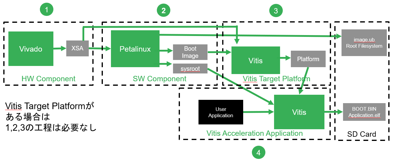
今回は上図の①の HW Component の簡単な Flow をご紹介いたします。
Vitis では Vitis Target Platform が無ければ Acceleration Application 開発ができません。ここでは Vivado で Vitis Target Platform で必要な Hardware 部分 (Zynq CPU、FPGA) の構成を行います。
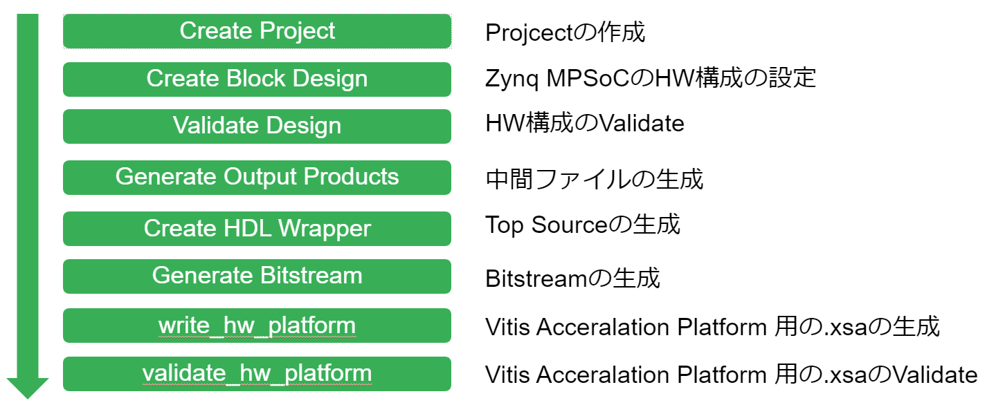
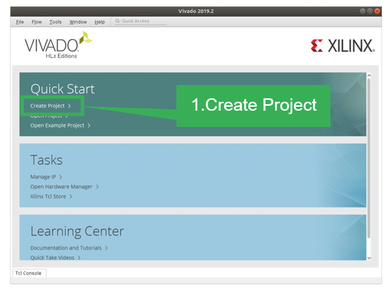
Create Project
Vivado で新規で Project を作成します。選択する Device は Zynq MPSoC をベースにします。Vitis Target Platform の構築は、Embedded の場合は Zynq 7000、Zynq MPSoC Series、Versal ACAP の ARM 社製 CPU 搭載 Device のみとなります。それ以外で FPGA のみの Device (MicroBlaze で SoC を構成する場合) では作成は出来ませんのでご注意ください。
Create Block Design
Vivado の IP Integrator を利用して、Zynq の Hardware 構成の設定を行います。ここでは、Zynq PS 部の設定、Clock および Reset の設定、Pratform Interface の設定を行います。
以下の図は IP Integrator を使用した Block Design の例です。
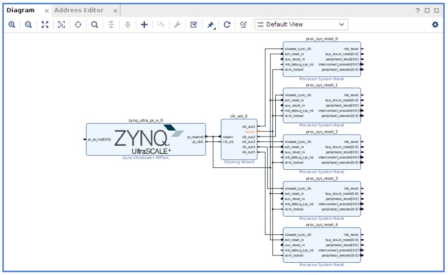
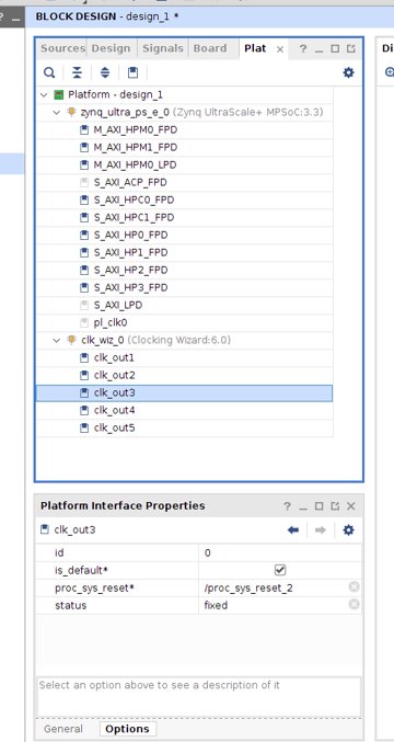
Vitis Target Platform では Acceleration Kernel で使用する Clock とその Clock に合わせた Processor 専用の System Reset を最低限用意する必要があります。User Logic がある場合は、この時に Block Design に含めます。
次に、Acceleration Kernel で使用する専用の Interface を設定します。Vivado の Menu より Windows -> Platform Interfaces を選択し、機能を Enable にします。あとは、User で利用したい Interface を指定することで、Vitis で Compile 実行時に Tool 側で判断して Interface に接続します。
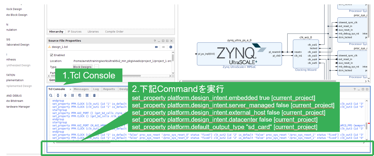
最後に、TCL Console から以下の Command を実行して、この項目は完了です。
set_property platform.design_intent.embedded true [current_project]
set_property platform.design_intent.server_managed false [current_project]set_property platform.design_intent.external_host false [current_project]set_property platform.design_intent.datacenter false [current_project]set_property platform.default_output_type “sd_card” [current_project]
Validate Design
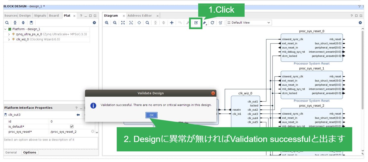
Hardware 構成で Clock、Reset などの接続に問題が無いか検証します。Diagram Tab にある Check Mark の Icon を Click することで実行が可能です。
Generate Output Products
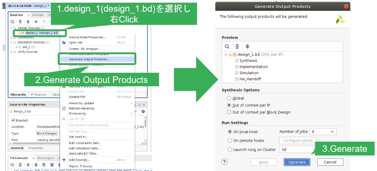
IP Integrator で構成した Hardware を、Bitstream の生成に必要な中間 Wrapper File を生成します。BLOCK DESIGN Tab で IP Integrator で生成した Design (.bd) を選択し、右 Click Menu より “Generate Output Products” を実行します。これで、IP Integrator で生成した IP Block の設定を反映した Wrapper HDL が吐き出されます。
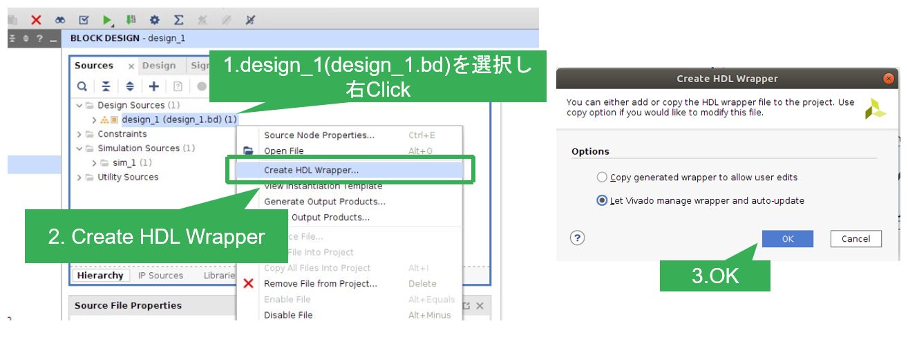
Create HDL Wrapper
先程の Generate Output Products と同じく、IP Integratorで作成した Design を選択し、右 Click Menu より “Create HDL Wrapper” を実行します。これで、Top module となる HDL が生成され Bitstream を生成することが出来るようになります。
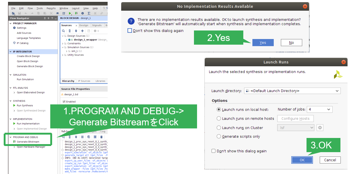
Generate Bitstream
Top module となる Wrapper HDL の生成が完了したあとは、FPGA の Configuration File の Bitstream の生成を実行します。
※Bitstream の生成は、必須ではありませんが Software との動作比較検証時、Zynq PL 部を必要とする Application を実行する場合に必要となるので、生成しておくと安心です。
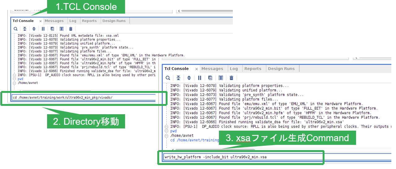
write_hw_platform
Bitstream の生成が完了したら、Vitis Target Platform で利用する .xsa を生成します。
※Vivado 2019.2 では TCL Command での実行でしたが、2020.1以降は Export Hardware で実行できるようになっております。
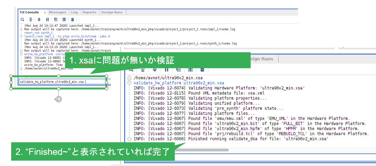
validate_hw_platform
最後は、Vitis Target Platform の Hardware の設定に問題が無いか検証します。Command を実行すると Console に “Finished ~” と表示されていれば完了です。
以上で、Vitis Target Platform の Hardware 編は完了です。次回は、Software 編で PetaLinux を利用した Kernel 構築の手順をご紹介いたします。
AVNET K.K. 仲見 倫